Difficulties in five-axis machining on aero-engine titanium alloy impeller
As a reusable component of the national manufacturing industry, the aerospace industry, its upgrading of high-tech equipment and products requires both “high, precise and sharp†CNC machining equipment, and urgently requires advanced manufacturing technology to meet the complexities. The product structure changes and the wide application of difficult materials.
Among the large number of aerospace components, aero engines are the core of the aircraft's power, and the main materials of the parts are titanium alloys and high-temperature alloys. Titanium parts are mostly used in the cold end of aero engines (fans and compressors, etc.), while hot end parts (turbines, etc.) are mainly high temperature alloy parts.
1. Processing difficulties analysis
The integral centrifugal impeller studied in this paper requires a surface roughness value of Ra = 1.6 μm. The blade surface is a free-form surface with a large curvature change, and the contour accuracy is required to be within 0.05 mm.
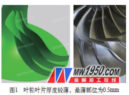
From the analysis of the structure of the impeller, due to the narrow flow path, the collision between the machining tool and the adjacent blade is very easy to occur, and the swing axis of the machine tool needs to have a large swing range, so as to facilitate the tool to avoid interference in a limited space. The blade root spacing is about 1.2mm, the root radius requirement is less than R2mm, and the blade length is more than 40mm. How to achieve rapid removal of the balance requires the combination of titanium alloy material characteristics, tool design and machine tool spindle rigidity. The thickness of the blade is thin, the thinnest part is 0.5mm, and the thickest part is only 3mm (see Figure 1).
How to overcome vibration during processing to achieve better surface quality? In addition to the high-speed spindle and the choice of tools for high-speed machining of titanium alloy materials, the dynamic performance of the machine tool in the linkage machining process is also required to be stable.
From the analysis of the impeller material, titanium alloy is widely used as the material of the impeller due to its excellent mechanical properties. However, titanium alloy is a difficult material in machining, and its processing difficulties are mainly manifested in the following points:
(1) High cutting temperature
Since the thermal conductivity of titanium alloy is very small (only 1/5 of iron and 1/14 of aluminum), the cutting heat generated during cutting is not easily transmitted, concentrated in a small range near the cutting zone and the cutting edge, and the cutting temperature Very high, causing the workpiece to burn, causing the tool material to soften and accelerate the wear of the tool, which is a remarkable feature of titanium alloy processing.
(2) The chemical activity of titanium is large
At high temperatures, it is easy to react strongly with oxygen, nitrogen, hydrogen, etc. in the atmosphere to form hard and brittle layers such as TiO2, TiN, TiH, etc., resulting in uneven hardness of the cut area and the uncut area, and the tool is unevenly stressed and intensified. Tool wear.
(3) Large elastic recovery
The elastic modulus of titanium alloy is 107.8GPa, which is about 1/2 of that of steel. Under the action of cutting force, it will produce large cutting deformation and large elastic recovery. In summary, how to improve the processing efficiency of such impellers (from 30h processing time to 18h processing time) and blade forming quality, it is necessary to comprehensively consider various factors to select suitable equipment and design a suitable process plan.
2. Processing plan
(1) Machine tool selection
In order to shorten the processing time, roughing requires a high efficiency margin. In the machining state of low speed and large depth of cut, the impact load will be beneficial to the machining stability of the tool within the maximum torque tolerance of the spindle.
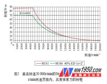
The machine tool selection must take into account the processing characteristics of the machined material. The blade is made of titanium alloy (Ti6Al4V), the cutting speed should be low, and the cutting temperature should be avoided during processing, so that the titanium alloy absorbs oxygen and hydrogen from the surrounding atmosphere, and the microstructure changes to strengthen the surface. Considering this kind of processing material, the cutting depth can be large, and the cutting edge can be cut below the hardened layer, which is beneficial to improve the tool life.
(2) Fixture
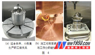
Tooling not only acts as a connection between the workpiece and the workbench, but more importantly, it can stabilize the workpiece during processing and prevent vibration. If a special fixture with vibration absorption function is used, it will be of great benefit to improve the surface quality of the workpiece.
At the same time, it should be noted that when the swing axis has a large swing angle (more than 90°) during machining, it is necessary to consider the minimum distance of the workpiece from the work surface to avoid collision interference between the spindle and the table, as shown in Figure 4b.
Figure 4a is a fixture for single-piece, low-volume production. For high volume production types, a dedicated pallet exchange positioning system is recommended as shown in Figure 4c.
(3) Cutting tool, machining process and cutting parameters
In order to optimize efficiency, we choose a dedicated titanium machining tool. The roughing tool selects a nose knife (φ8R 1mm) with a diameter of 8mm to suit the process characteristics of low speed, deep processing and large chip removal. The cutting edge of the tool is serrated to prevent the formation of large particle chips and facilitate the detachment of the chips. In the roughing process setting, the depth of cut (a p ) is up to 8 mm, and the tool will be subjected to the reverse force when it is full-cut. Because the cutter is easy to be pulled out by the ordinary spring ferrule, the side-lock is selected. Tightening the handle. Roughing tool path 1: In the middle of the two blades, the five-axis linkage mode is full-cut, the single-layer depth is 8mm; then it is offset to the sides, the maximum lateral feed (a e ) value is 6mm; the maximum swing angle is reached. (A-axis) -102.6° (see Figure 5). This process scheme greatly shortens the processing time of the flow path opening, and the specific process parameters are shown in Table 1.


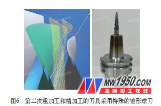
According to the blade root rounding specification (R≈1.5mm) and the minimum distance of the blade outer edge in Fig. 6 (9.9mm), the second roughing and finishing tool uses a special cone ball cutter: the top is R1.5mm The ball has a diameter of 8 mm and a 6° cone angle in the middle. At the same time, in order to be able to adequately cool the machining tools in the deep and narrow space and to facilitate the chip discharge flow path, a hot-lifting shank with a central inner cooling passage should be considered (see Figure 6).
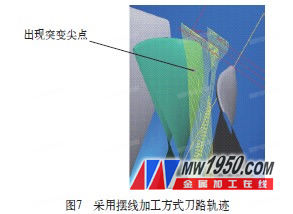
Roughing Path 2: For the narrow section of the runner root, we try two possible process options. The first scheme adopts the cycloidal processing method to gradually remove the margin from the outside to the inside. The single layer processing depth is 12mm, which is divided into two layers, and the lateral feed control is 0.13mm, which can realize large depth of cut processing and increase the amount of chip removal. However, with cycloidal processing, there is a sudden change in the path of the tool entering the flow path space, which is likely to cause the tool to chip. The process parameters are shown in Table 2, and the tool path is shown in Figure 7.
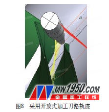
In the second processing scheme, in order to avoid the tool processing the entity at the cusp of the mutation. The open machining knives are used to first cut the balance between the two blades. The single layer has a depth of 2 mm and a total of 12 layers. Then, the cycloid machining method is adopted at the bottom of the flow passage, and the cutting edge of the tapered cutter is sufficiently long (32 mm) to be gradually processed into position by the side edge. The tool path is shown in Figure 8.
After the rough allowance is completed, the limiting factors for finishing the blade and the runner are relatively small.
3. Conclusion
Combined with the material characteristics of the machined parts and the characteristics of the product structure, how to effectively improve the efficiency and ensure the quality of the workpiece is the focus of engineering and technical personnel research.
Application:
Huge power range from 2.2KW~160KW
Support up to 128 stops
Speed up to 4 m/s ( Up to 6m/s soon)
Support up to 8 car group control with DBD system
Meet the EN81-20 standard, UCMP, door lock short detection, door bypass function, pit inspection function Selective collection
Encoder supported : SIN/COS & EnData & ABZUVW & ABZ
Feature:
Field proven high speed technology utilizing KEB F5 inverter and AFE (Active Front End) for regenerative function
ELGO landing system for absolute floor encoding and eliminate hoist way terminal switches
Support UCMP function
ETSL function for reduce stroke buffer applications
Advance isolated CAN ports for stable communications
Applications:
Up to 64 stops.
Speed up to 8 m/s.
Simplex, duplex, and up to 6 car group.
Kinetek Or Nidec Controller,Nidec Controller,Kinetek Motor Controller,Nidec Motor Controller
Suzhou Keffran Parts Co.,ltd , https://www.keffran-elevatorsmart.com