Tool radius compensation principle and compensation rules
2024-06-07 14:05:49
During the machining process, the wear of the tool, the actual tool size and the tool size specified during programming, and the replacement of the tool will directly affect the final machining size and cause errors. In order to minimize machining errors caused by tool size changes, etc., CNC systems usually have tool error compensation. Through the tool compensation function command, the CNC system can automatically machine the parts that meet the program requirements according to the input compensation amount or the actual tool size.
1. Tool radius compensation principle
(1) The concept of tool radius compensation
When milling the contour of a workpiece with a milling cutter, the motion path of the tool center is not the actual contour of the machined workpiece. As shown in the figure, when machining the inner contour, the tool center should be offset to the inside of the workpiece by a certain distance; when machining the outer contour, the same tool center should also be offset to the outside of the workpiece by a certain distance. Since the numerical control system controls the tool core trajectory, the tool core trajectory is calculated according to the part contour size during programming. The contour of the part may require three steps of rough milling, semi-finishing and finishing milling. Since each machining step has different machining allowances, they all have corresponding tool core trajectories. In addition, after the tool wears, it is also necessary to recalculate the tool path, which will increase the complexity of programming. In order to solve this problem, a number of storage units have been specially designed in the numerical control system to store the machining allowance and the tool wear amount of each step. For NC programming, you only need to write the nominal tool path according to the tool radius value. The machining path and the tool path change caused by the tool wear are automatically calculated by the system to generate the NC program. Further, if the tool radius value is also registered in the memory cell, the programming work can be simplified to program only by part size. This simplifies programming and increases the readability of the program.
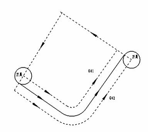
Tool radius compensation principle
(2) Mathematical processing of tool radius compensation
1 basic contour processing
To perform tool radius compensation according to the contour size, it is necessary to calculate the motion trajectory of the tool center. Generally, the contour control of the CNC system is usually limited to straight lines and arcs. For a straight line, the tool center trajectory after the tool compensation is a straight line parallel to the contour line. Therefore, as long as the start and end coordinates of the tool center trajectory are calculated, the tool center trajectory can be determined; for the arc, the tool offset The tool center trajectory is an arc that is concentric with the specified contour arc. Therefore, for the tool radius compensation of the arc, the starting point, end point, and center coordinates of the tool center trajectory arc need to be calculated.
2 sharp corner processing
In an ordinary CNC device, the contour trajectories that can be controlled are only straight lines and arcs. The connection modes are: straight line and straight line connection, straight line and arc connection, arc and arc connection. The figure shows the various transitions when the line is connected to the straight line. The programming path is OA→AP.

Straight to straight left tooling
(a), (b) shortened conversion; (c) extended type conversion; (d) insert type conversion
In Figs. (a) and (b), AB and AD are tool radius values, and the intersection of tool center trajectory IB and DK is C. The coordinate value of intersection point C is obtained by the numerical control system. The actual tool center trajectory is IC→CK. The method of finding the intersection point fundamentally solves the overcut phenomenon of the tool during the inner contour machining. Since IC→CK shortens the length of CB and DC with respect to OA and AP, the inner contour transition of this intersection is called shortened conversion, and the intersection is the core task.
In Figure (c), point C is the intersection of IB and DK extension line. The coordinates of intersection point C are obtained by the numerical control system. The actual tool center trajectory is IC→CK. By the same token, this outer contour transition is called an extended transition.
In Figure (d), if the method of finding the intersection of IB and DK is still used, it is bound to increase the non-cutting idle travel time of the tool excessively, which is obviously unreasonable. Therefore, the tool compensation algorithm uses the insert type conversion here, that is, BC=C/D=R, the numerical control system finds the coordinates of C and C/point, and the tool center trajectory is IB→C→C/→DK, that is, in the middle of the original track. The CC/straight line segment is inserted, so it is called an insert type conversion.
It is worth mentioning that some CNC systems use a circular arc with a radius of the tool radius for the above-mentioned elongated or inserted type. Obviously, this treatment is simpler. However, when the tool makes a sharp arc transition, the contour transition point is always in the cutting state, the machining stops, and the process is poor.
(3) Execution process of tool radius compensation
Tool radius compensation is not done by the programmer. The programmer indicates in the program where to perform tool radius compensation, indicating whether to perform left or right tool compensation, and specify the tool radius. The specific work of tool radius compensation is performed by the tool radius compensation function in the CNC system. According to the ISO regulations, when the tool center path is on the right side of the forward direction specified by the program, it is called right tool compensation, which is represented by G42; otherwise, it is called left tool compensation, which is represented by G41.
The execution process of tool radius compensation is divided into three steps: tool compensation, tool compensation and tool compensation.
1 knife repair
That is, the tool approaches the workpiece with the starting point, and the tool center direction G41/G42 determines whether the tool center track is extended or shortened by a tool radius value based on the original programming track. as the picture shows.
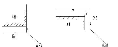
Tool repair
2 knife repair
Once the tooling is established, it is maintained until it is cancelled. During the tool offset, the tool center path always deviates from the tool path by a tool radius value. At the transfer, three straight-line transitions of elongation, shortening and insertion are used.
3 knives to cancel (G40)
That is, the tool is withdrawn from the workpiece and returned to the starting point. As with tool compensation, the tool center path is also longer than the programmed path or by a distance of one tool radius.
The tool radius compensation is performed only in the specified two-dimensional coordinate plane, and the plane designation is represented by code G17 ( X-Y plane), G18 ( Y-Z plane), and G19 ( X-Z plane).
2. Tool radius compensation programming rule
Before starting the cutting process, the tool radius compensation (usually on the XOY plane or the plane parallel to the XOY plane) is added in advance to the position away from the workpiece, and then the Z-axis direction is cut. In order to ensure that the correct workpiece contour is obtained after the program is run without overcutting, the structure of the machining program must be paid attention to during programming.
As shown in the figure, in the XOY plane (or in the plane parallel to the XOY plane), use the tool radius compensation function (with Z-axis movement) for contour cutting, set the starting point at (0,0,100), when the tool radius compensation When starting from the starting point, due to the Z-axis movement when approaching the workpiece and cutting the workpiece, overcutting occurs when the following procedure is added, and the system does not stop the alarm.
As shown in the figure, in the XOY plane (or in the plane parallel to the XOY plane), use the tool radius compensation function (with Z-axis movement) for contour cutting, set the starting point at (0,0,100), when the tool radius compensation When starting from the starting point, due to the Z-axis movement when approaching the workpiece and cutting the workpiece, overcutting occurs when the following procedure is added, and the system does not stop the alarm.
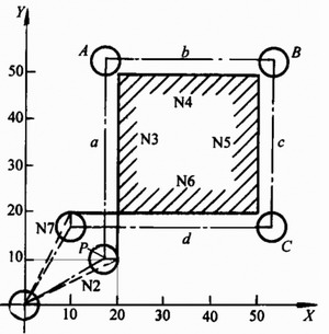
a) Correct compensation track
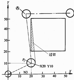
b) Compensation path with overcut phenomenon Tool radius compensation track
O 0001
N1 G90 G54 S1000 M03 ;
N2 G00 Z100 ;
N3 X0 Y0 ;
N4 G01 G41 X20 Y10 D01 F100 ;
N5 Z2 ;
N6 Z-10 ;
N7 Y50 ;
N8 X50 ;
N9 Y20 ;
N10 X10 ;
N11 G00 Z100 ;
N12 G40 X0 Y0 ;
N13 M05 ;
N14 M30 ;
According to the tool radius compensation function programming rule, after the tool radius compensation is established in the XOY plane (or in the plane parallel to the XOY plane), the two Z-axis movement commands cannot be continuously displayed, otherwise the compensation position will be incorrect. When the radius compensation is established from the N4 block, the CNC system can only pre-read the two subsequent blocks, while the N5 and N6 blocks are Z-axis movement commands, and there is no coordinate movement in the XOY plane. It is impossible to judge the vector direction of the next compensation. At this time, the system does not alarm, and the compensation is still performed. However, after the execution of the N4 block, the target point of the tool path changes, no longer the P point in the figure, but as shown in the figure. The P1 point, which produces an overcut (shaded in the figure). To avoid this overcut, you can select a safe position that does not interfere before establishing the radius compensation, so that the Z axis approaches the workpiece with rapid motion and then feeds to the depth of cut at the feed rate. Change the above procedure to:
N1 G90 G54 S1000 M03;
N2 G00 Z100;
N3 X0 Y0;
N4 Z5;
N5 G01 Z-10 F100;
N6 G41 X20 Y10 D01;
N7 Y50;
N8 X50;
N9 Y20;
N10 X10;
N11 Z100;
N12 G40 X0 Y0 M05;
N13 M30.
By using this block for processing, overcutting can be avoided.
3. Application of tool radius compensation function
(1) After the tool is changed due to wear, re-grinding or renewing, it is not necessary to modify the program. Just input the changed tool diameter in the tool parameter setting. As shown in the figure, 1 is the unworn tool, 2 is the worn tool, and the diameters of the two are different. The same procedure can be applied by changing the tool radius r1 in the tool parameter table to r2.
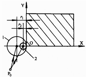
The tool diameter is changed and the machining program is unchanged.
(2) With the same program and the same size of the tool, the tool radius compensation can be used for roughing and finishing. As shown, the tool radius is r and the finishing allowance is â–³. In the roughing process, when the tool diameter D=2 (r+â–³) is input, the dotted line contour is machined. In the finishing process, the same program and the same tool are used, but the input tool diameter D=2r is used to machine the solid line contour.
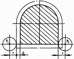
P1 - rough machining core track
P2——finishing tool path traversing rough machining with tool radius compensation
(3) In the modern numerical control system, some have the function of three-dimensional tool radius compensation. For the four- and five-coordinate linkage CNC machining, the tool compensation function is not yet available, and the tool radius must be considered in the tool position calculation.
Steel Structure Office,Prafab Steel Structure Office,Prefab Steel Office,Steel Structure Office Building
Foshan Shengbang Steel Structure Co.,Ltd , https://www.sbsstructure.com