Multi-axis UG programming of impeller
Complex profiles are common in engineering practice. The most typical representative is the impeller. The processing technology of the integral impeller has always been an important issue in the manufacturing industry. According to the metal processing online reporter, at present, the impeller processing special software mainly includes the MAX-5, MAX-AB of the US NRCC, the integral impeller processing module of the Swiss Starrag CNC machine tool, and the special impeller processing such as Hypermi ll. software. In addition, some general-purpose software such as UG, CATIA, Pro/E, etc. can also be used for integral impeller machining. In general, the research and application in the field of impeller processing in China is still far from the developed countries. It has not yet passed the high-performance impeller manufacturing technology such as narrow channel, large torsion angle and small hub ratio. Therefore, its processing technology is studied. It is imperative.
Overall impeller structure characteristics and processing difficulties
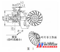
The structure of the integral compressor impeller is shown in Figure 1. The outlet diameter is 90 mm, there are 15 blades, the exit blade height is 3.2 m, the impeller inlet diameter is 46.6 mm, the inlet blade height is 11.3 mm, and the blade thickness is the thinnest. 0.4mm, the minimum spacing between adjacent blades is 2.7mm.

The difficulty of processing the compressor impeller is as follows: 1 The blade is long, the machining channel is narrowed, and the processing difficulty is increased. 2 The finishing tool has a diameter of 2mm, the rigidity is poor and easy to break, and controlling the cutting depth is the key. 3 The surface of the impeller is a free-form surface, a narrow flow path, a large twist angle of the blade, and a backward tilting tendency, which is easy to cause interference during processing. 4 The radius of curvature of the leading edge of the leading edge varies greatly, and the angle of the machine tool changes greatly during the machining process, and it is difficult to realize the processing of the surrounding blade.
Compressor impeller processing scheme
The integral impeller machining must be integrally formed by a hub and a blade in a blank. The processing scheme is as follows: (1) In order to improve the strength of the overall impeller, the blank is generally forged, and then the turning of the reference surface is performed. The basic shape of the impeller body.
(2) The opening and closing of the impeller air flow passage should be selected in the middle position of the air flow passage. The ball taper shank milling cutter is used to run parallel to the air flow passage, and the groove bottom has a certain machining allowance on the surface of the hub.
(3) The groove forming process of the impeller air flow passage and the rough machining of the blade. Because the impeller groove is narrow and the blade is severely twisted, and the UG numerical control machining programming needs to determine the cutting area according to the driving surface, the roughing of the blade needs to select the driving surface as The offset surface of the blade surface is adjusted by adjusting the parameters of the trimming and extension multiple times in the driving method-streamline editing and ensuring that the hub surface is not cut.
(4) Finishing of the blade and the hub is finished under a uniform margin to ensure a good surface quality. Considering the minimum spacing between adjacent blades is 2.7mm, in order to prevent interference, the φ2mm ball-end taper shank is used. Knife, half cone angle 2 °, shank diameter 8mm.
(5) Root rounding treatment The surface of the previously milled blade does not include the root rounded portion, so we finally need to finish it by one pass.
The above procedures must be performed after indexing, rotating, and machining the entire hub or blade to perform the next procedure to ensure uniform stress release and reduce machining deformation errors.
NC programming of compressor impeller
1. Process flow
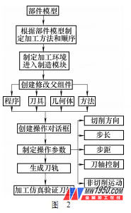
When programming with UG, it is usually guided by the flow chart shown in Figure 2 to create the tool path of each operation and through the entire process.
2. NC programming

(1) Establish a parent node group
1 Under the tool node, add all the tools used for machining and set the tool parameters. 2 Under the Geometry node, set the machining coordinate system. 3 Under the method node, set the spindle speed, feedrate, and display color of the tool path during roughing, semi-finishing, and finishing.
(2) Slotting processing of impeller air flow passage
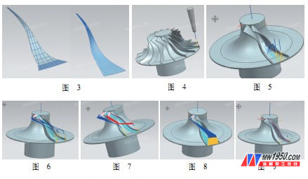
The flow path surface is extracted. The U and V parameter lines are shown in Figure 3 (left). Because the machining of the impeller channel needs to be along the airflow direction, the U and V parameter lines of the flow channel are rearranged so that the U parameter line or the V parameter line is along. Airflow direction. The rearranged V parameters are shown in Figure 3 (right) and are in the direction of the airflow.
The flow channel grooving process uses Variable Contour. The deeper the machining depth, the more serious the interference. To avoid the interference of Figure 2, the avoidance geometry can be established. The direction of the tool axis and the width and length of the tool can also be manually controlled. , depth, etc. to avoid interference to achieve the purpose of roughing of the flow path, in order to improve the processing efficiency, the workpiece is three-layer cutting (UG generation tool path shown in Figure 4).
The parameters of the program are set as follows: 1 The driving method uses streamlines. The 2 drive curves are respectively selected by the three curved surfaces that are offset by the flow path surface, and the position and length of the parameter path are adjusted in the trimming and extending. 3 The roughing cutting mode is selected as one-way, the step is selected as the number, and the step number is selected as 3, 2, and 5 respectively. The 4-axis control mode is interpolation, adding data points and changing the vector direction in the interpolation tool axis to avoid interference with the left and right blades.

(3) Expansion processing of impeller air flow passage
The slotting process is similar to slotting, except that the bottom runner surface (with a margin) is removed as much as possible (see Figure 5).
(4) Further expansion and roughing of the blade
After the groove forming process, most of the remaining amount of the flow path has been processed. In order to ensure a uniform machining allowance before finishing and improve the final surface quality, this step is to continue the groove expansion and rough machining of the blade. The machining drive curve selects the offset face of the blade (see Figure 6).
(5) Finishing of the blade
General parameters of blade finishing (the generated tool path is shown in Figure 7): 1 drive curve selects the blade surface. 2 Adjust the parameter path position in the trim and extension to prevent the tool from cutting into the bottom of the flow path. 3 cutter axis control mode is relative to the drive body, the key is to choose the forward tilt and roll angle parameters. 4 Set the non-cutting movement parameters, and select the tool in the cutting direction and the tool axis to retract. 5 The remaining amount of the part in the cutting parameters is set to zero.
(6) Flow path finishing
In order to meet the final surface quality, the flow path must be finished. The drive curve is selected to rearrange the flow path surface of the U and V parameter lines of the flow path. The tool axis control mode is interpolation, and the data points are added to the interpolation tool axis. And change the vector direction angle to avoid the machining of the tool path and simulation generated by the left and right blades (see Figure 8).
(7) Blade root rounding processing
After the first few steps of processing, there is a small amount of margin at the root of the blade, which can be cut through a similar process of trimming and extending the adjustment parameters while avoiding the generation of undercuts. The resulting machining tool path and simulation are shown in Figure 9.
sliding folding partition walls,office moveable walls,soundproof movable panels,divisions movable walls,soundproof portable partition walls
Guangzhou MQ Acoustic Materials Co., Ltd , https://www.movablepartitionwall.com