CAD/CAM applications in high speed machining (4)
(3) Use a continuous method, such as the offset path is usually better than the balanced path.
(4) Avoid vertical cutting, which should be cut from the outside of the material.
(5) In the critical area of ​​the part, ensure that the finishing path of the different steps will not be repeated, otherwise the tool marks will appear.
(6) Try not to change the knife and use a single tool to finish the critical area. Tool setting errors often result in tool marks on the machined surface after finishing.
(7) Long tools are prone to wear and should be used as short as possible. If possible, consider repositioning the part and using a short tool for machining in areas that are difficult to machine.
Third, the conclusion
(1) High-speed machining requires strict requirements for each part of the workpiece. The basic requirement is to use appropriate physical equipment and accurately specify the relevant parameters. Although it is difficult to specify which CAD and CAM functions are required for high-speed machining, it is certain that CAD and CAM have a significant impact on the quality and stability of high-speed machining.
(2) The CAD model used for high-speed machining must accurately express the shape of the model to be machined, which means that the accuracy of the model must be higher than the machining accuracy, and if possible, the model features that do not need to be milled are deleted or covered.
(3) High-speed machining equipment must be equipped with sufficient CAM programmers to ensure that the machine uses the best procedures. One of the ways to improve the quality of programming is to allow machine tool builders to program the machining process on the shop floor while ensuring that CAM operators and machine tool operators have received good technical training.
(4) If you want to obtain good high-speed machining results, the most effective method is to carefully arrange the processing sequence and use the processing conditions provided by the CAM system.
Previous page
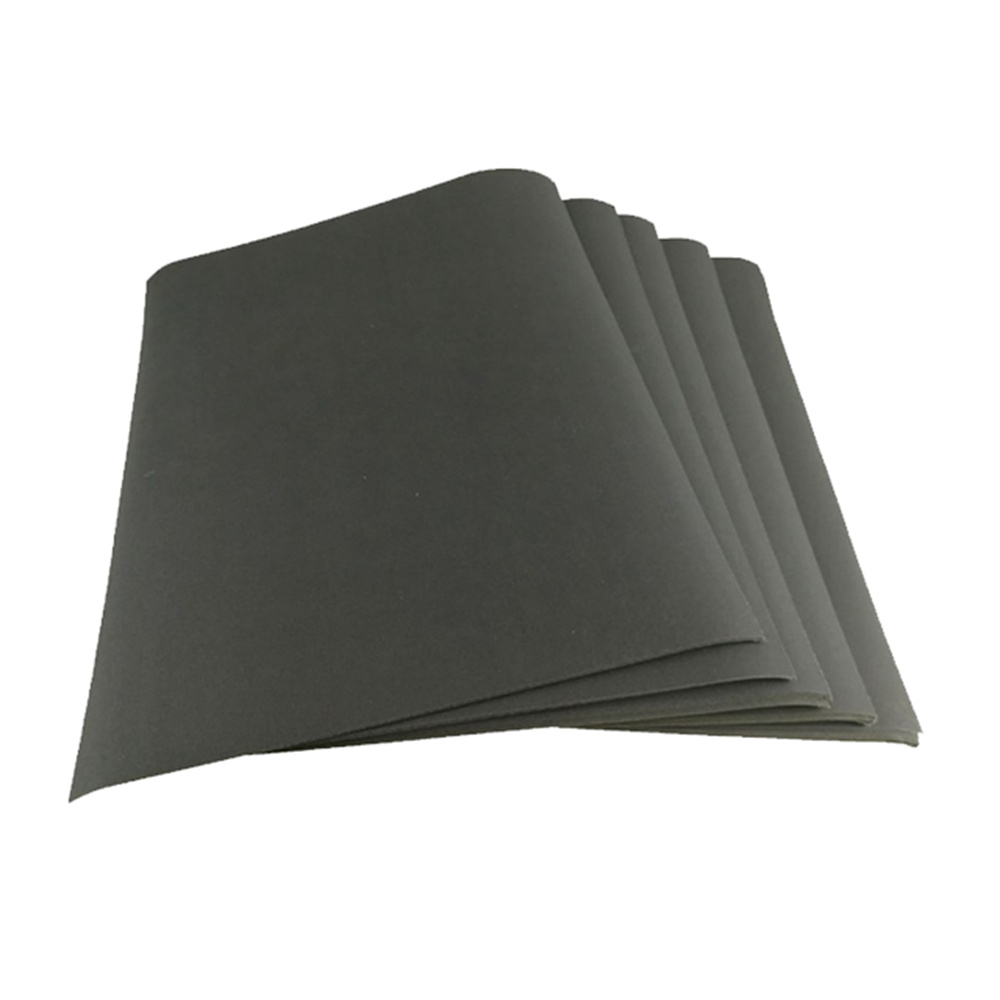
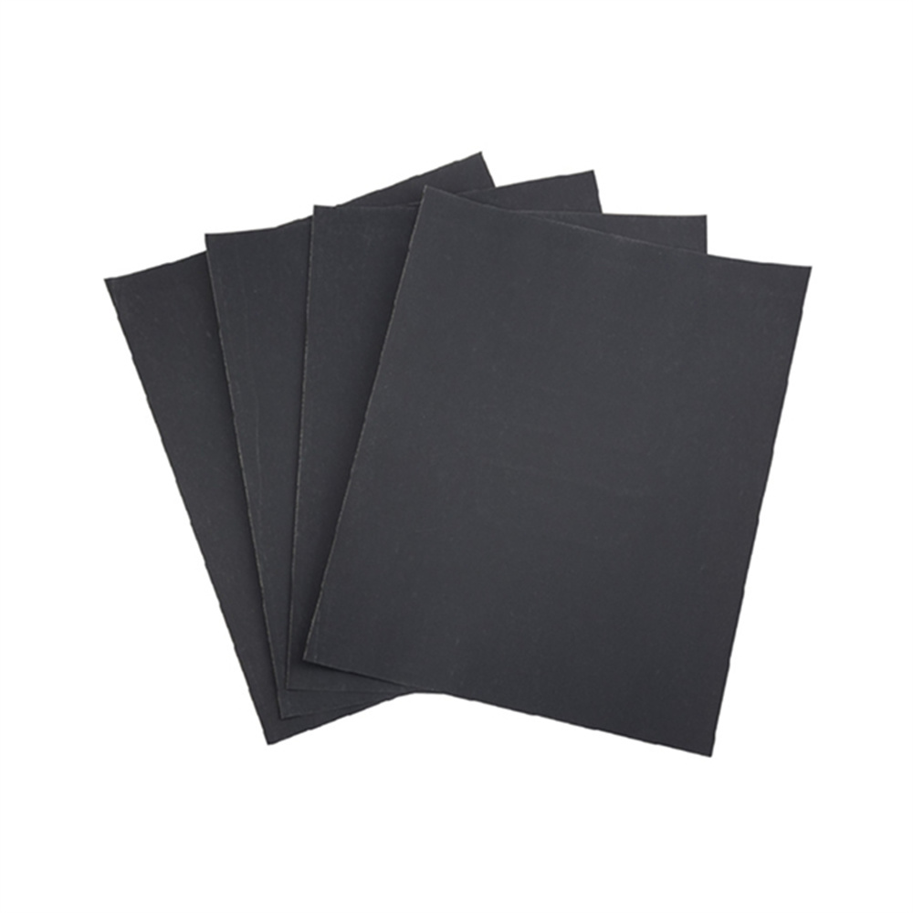
Product Name: silicon carbide coated multi grid abrasive sandpaper wet or dry sandpaper
Material: Silicon carbide
Size: 230mm x 280mm, 93*230mm
Substrate: Paper backing
Grit: 60#, 80#, 100#, 120#, 150#, 180#, 240#, 280#, 320#, 360#, 400#, 500#, 600#, 800#, 1000#, 1200#, 1500#, 2000#, 3000#, 5000#, 7000#
Coating: Electro coated
Feature: Waterproof, flexible, dual use, durable, cost-effective.
Application: Used for grinding and polishing metal, wood, glass, ceramics, plastic, varnish, stone, wall etc.
Grinding & Polishing Sandpaper
Soft Paper Backing / Uniform Sand / Wet & Dry Use
How to Choose Grit
From 60# to 2000#
Grit Size Introduction Suitable for
60# - 220# coarse sand, for hard and rough products Metal, wood, wall, stone
240# - 500# Frequently used, for secondary grinding Wall, furniture, stamp
600# - 1500# Fine sand, common used for grinding and polishing Metal, bodhi, amber, honeystone, jade and plastic
2000# and above Super fine, for polishing Amber, honeystone, bodhi, metal, nail, mirror polish etc.
Packing Details: 100 pcs/box, 1000 pcs/CTN.
Lead Time: For small quantity, 3-5 days after payment done.
For large quantity, can be negotiable.
Delivery Methods: by sea, air, expresses like DHL, Fedex, UPS, EMS etc.
The related abrasive products we can supply is Flap Disc Adhesive , Abrasive Flap Disc, and Flap Disc Making Machine, Flap Wheels , Flap Wheel Machine , Abrasive Sanding Disc, if you have any needs about abrasive tools, please kindly feel free to contact us.


Abrasive Sandpaper,waterproof sandpaper,Electric Sandpaper,Sandpaper Waterproof,Silicon Carbide Sandpaper
Zhengzhou Jiading Abrasive Manufacturing Co.,Ltd , https://www.abrasive-jd.com