Allowable deflection analysis of modern machine tool spindles (4)
1. From the historical background, according to the literature [5], [6], it is the research results of the 40-50s, the production level at that time determined that the rigidity requirements of the machine Tool are relatively low. Both Leishov and Achelcon are based on the stiffness requirements of the geared shaft, and mainly refer to the maximum deflection between the bearings, and do not analyze the maximum deflection of the finishing and semi-finishing machines. In recent years, the design textbooks published in Russia, see the literature [4], have deleted the discussion of [y]=0.0002L. It shows that with the improvement of production level and design practice, it has been reflected that this type has great limitations and should not be used as the calculation standard for permissible deflection.
2. From the actual production, it is indicated that the evaluation of the spindle stiffness should be based on the performance. For different applications (mainly machining accuracy), the spindle has different deformation requirements. For the spindles of finishing and semi-finishing machines, the spindle stiffness should be based on the accuracy of the workpiece. Since the deflection of the cutting point at the spindle end directly affects the machining accuracy, the deformation should refer to the deflection of the spindle end, that is, the stiffness of the spindle should be measured by the stiffness of the shaft end. Normally, the spindle should be allowed to allow 1/3 of the radial runout δ. When designing the spindle, the spindle allows the radial runout δ to be usually specified as 1/3 of the dimensional tolerance. Therefore, for machine tools for finishing and semi-finishing, the spindle end allows deflection [y] ≤ /9. For the spindle of a roughing machine, the stiffness of the spindle should be based on the normal operation of the spindle drive. Since the deflection in the middle of the spindle support affects the working of the transmission gear, it reflects the rotation angle of the front and rear bearings of the spindle to some extent. Therefore, the deformation should refer to the deflection between the shafts, that is, the stiffness of the main shaft should be measured by the stiffness between the shafts. (According to the stiffness requirements of the gear transmission shaft, take [y]=0.0002L, the two cannot be mixed)
V. Conclusion
[y]=0.0002L is based on the stiffness requirements of the geared shaft. It is the allowable deflection between the shafts that meets the normal working conditions of the gear. It cannot be used as the allowable value of the deflection of the end of the spindle, and can not be used as finishing and The deflection control condition of the semi-finishing machine spindle can only be used as the inter-axis deflection control condition of the roughing machine spindle. The allowable value of the spindle stiffness is based on the performance of the use and the relevant spindle parameters are determined accordingly.
references
[1] Dai Wei, Editor-in-Chief, "Metal Cutting Machine Design", Mechanical Industry Press, 1981
[2] "Metal Cutting Machine Design" Writing Group "Metal Cutting Machine Design" (Revised) Shanghai Science and Technology Press, 1985
[3] Yang Rongbai, Editor-in-Chief, "Metal Cutting Machine Tools---Principles and Designs", Huazhong Institute of Technology Press, 1987
[4] "Memaллope yщue Cmaнкuкypcoво u дunлоное проепmupoвa-нue" 1987 .M .
Opлuкoв. B .H .шuшкuн
[5] Л . H. Lishetov, "Calculation of Machine Tool Parts", Soviet National Machine Manufacturing Books Publishing House, 1945 Edition, Zhao Weizhen, Zhao Shengbin, Zheng Ming, Commercial Press, 1956
[6]Pacyem u oнcmpyupo вaнueмemaлope yшuх Cmaнкoв Maшгuз 1952. HC Aycpкaн
[7] Feng Xin'an, Editor-in-Chief, Mechanical Manufacturing Equipment Design, Mechanical Industry Press, 2006
[8] Cheng Daxian, Editor-in-Chief, Mechanical Design Handbook, Axis and Its Connections, Chemical Industry Press, 2006
Previous page
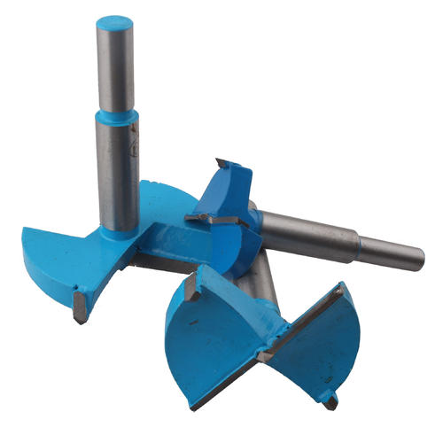
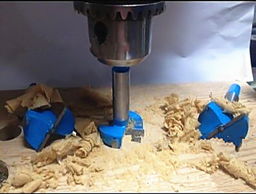
Forstner bits, flat-bottomed to drill holes in wood materials, they can cut on the edge of a block of wood, and can cut overlapping holes; for such applications they are normally used in drill presses or lathes rather than in hand-held electric drills. Because of the flat bottom of the hole, they are useful for drilling through veneer already glued to add an inlay.
The bit includes a center point which guides it throughout the cut (and incidentally spoils the otherwise flat bottom of the hole). The cylindrical cutter around the perimeter shears the wood fibers at the edge of the bore, and also helps guide the bit into the material more precisely.
Forstner bits have radial cutting edges to plane off the material at the bottom of the hole. The bits shown in the images have two radial edges; other designs may have more. Forstner bits have no mechanism to clear chips from the hole, and therefore must be pulled out periodically.


Forstner Bits,bosch forstner bits,colt forstner bits
Behappy Crafts (suzhou)Co.,Ltd , https://www.jshaoyue.com