A new process for improving the machining accuracy of multi-cylinder machine
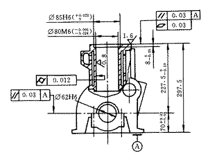
 figure 1 |
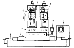
 1. Slide base 2, 4. CNC slide 3. Column 5. Bun 6. Milling head 7. Console 8. Control cabinet Figure 2 Double-station semi-flexible CNC milling and boring machine |
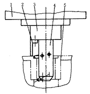
 1. Taro box 2. Positioning rod 3. Sliding sleeve 4. Mast 5. Workpiece Figure 4 Schematic diagram of the boring tool positioning |
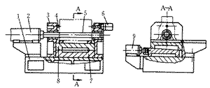
 1. Fixture base 2, 6, 9. Cylinder 3. Guide seat 4. Thrust positioning block 5. Positioning rod 7. Lower wedge 8. Upper wedge Figure 5 Schematic diagram of the fixture structure |
1 question raised
The schematic diagram of the cylinder bore and the stop of the three- and four-cylinder multi-cylinder diesel engine produced by our company is shown in Figure 1. The traditional processing method is: fine milling of the top surface (positioned on the bottom surface) - fine cylinder bores and stops (positioned by the bottom and bottom pins), respectively, on two machine tools. Mainly produces the following quality problems: (1) the spindle hole center to the top surface size of 227.5mm can not meet the requirements of the drawings; (2) the parallelism of the spindle hole axis and the top surface can not meet the requirements of the drawings; (3) The depth of the mouth is not up to the drawing requirements. Seriously affected the quality of the diesel engine. To this end, we adopted a new process method to develop and design a semi-flexible CNC combined machining machine with a milling top surface and a double-station (Fig. 2). After half a year of use, the effect is very significant.
2 processing technology analysis
The precision requirements and main processes of the workpiece are shown in Figure 1. The process dimension chain is shown in Figure 3. Its design basis is at the center of the spindle hole, which does not coincide with the process reference (process reference is on the bottom), and the dimension N is in the process. The middle is naturally formed. It is a closed ring with a tolerance of d N =0.10mm and the reference misalignment error is d A2 =0.06mm. The machining error d A1 = d N - d A2 =0.04mm is allowed, and the machining tolerance is too Small, can not guarantee the processing accuracy. The parallelism of the spindle hole axis to the bottom surface is 0.03 mm, and the parallelism requirement of the spindle hole to the top surface cannot be guaranteed at all. The boring of the cylinder hole stop, although the tool cutting is processed by the top surface positioning, but due to the influence of the top chip during the boring process, the positioning is not accurate and the positioning accuracy of the hydraulic dead iron is affected (Fig. 4). The machining accuracy of the stop cannot be guaranteed.
 Figure 3 processing top dimension chain |
3 Process improvement
From the above process analysis, it is known that to ensure the distance from the center to the top of the spindle (227.5 0 -0.10 ) mm and its parallelism requirements, the best way is to reduce the reference misalignment error, so that the positioning reference coincides with the design basis, even if d A2 =0. This allows the machining error d A1 = 0.10 mm, which is better ensured during machining, that is, the top surface is machined by the spindle hole. However, the positioning of the spindle hole should solve three problems, one is the anti-rotation positioning of the workpiece, the other is that the fixture must have sufficient rigidity, and the third is to be convenient to use.
The control of the depth of the cylinder bore is also a difficult technical problem. It is useful in the same industry for the cylinder bore and the stop – the milling surface, but also the use of numerical control technology, but there is a problem, can ensure the depth of the mouth, it is not easy to guarantee The size from the center of the spindle hole to the top surface. To this end, we use the spindle hole positioning, apply numerical control technology, develop and design the milling top surface - the cylinder bore and the stop double-station semi-flexible CNC combined boring and milling machine.
4 tooling equipment design
The overall design of the machine tool is shown in Figure 2. The machine tool selects the SKY CNC system of Nanjing Sikai Electronics Co., Ltd.: the number of control axes is X, Y, Z; the motion control mode is semi-closed loop; the pulse equivalent is 0.005mm; Chinese programming (the numerical control part detailed function) slightly). In the design of boring head and milling head, in order to improve the machining accuracy and productivity, consider adopting new tool materials, milling cutters are used for coating blades, and boring tools are made of PCBN cubic boron nitride. Therefore, boring heads and milling heads are adopted. It can adapt to high-speed cutting, high-precision diamond head and fine milling head structure (slightly omitted).
The fixture structure is shown in Figure 5. The working principle is as follows: before the workpiece is clamped, the positioning rod 5 is located at the left extreme position, the workpiece is mounted, the positioning rod 5 is inserted into the spindle hole and enters the guiding sleeve of the right guiding seat, and the workpiece is mainly positioned, and then the workpiece is lifted ( At this time, the bottom surface of the workpiece and the upper surface of the wedge 8 have a gap of 0.3 to 0.5 mm. The cylinder 6 is moved to the left to make the workpiece complete the thrust positioning, and then the cylinder 9 pushes the wedge 7 to the right to make the wedge 8 gradually rise close to the bottom surface of the workpiece. Until the paste is combined and clamped. The wedges 7, 8 not only have the function of preventing the workpiece from being anti-rotation, but also can clamp the workpiece at the same time, and more importantly, can enhance the support rigidity of the workpiece positioning and clamping.
The working process is as follows: the workpiece is mounted on the fixture (the fixture is mounted on the longitudinal table), firstly, the milling head slides down quickly into position in the milling working position, and the workpiece enters the first station along with the fixture for finishing the top surface. (The workpiece is positioned on the fixture with the spindle hole). After the milling is completed, the milling head slides back and retracts. The longitudinal table advances quickly and enters the second station. The boring head slides down fast - Gongjin - é•—Stop the surface in place, delay at the same time, complete the spindle positioning, and move the vertical table to the right (1mm) to prevent the knife tip from scratching the workpiece surface. Then the boring head slides back quickly. After the position, the vertical table Return to the first station, remove the workpiece, and the cycle is complete.
Since the equipment and fixture are designed with the problems of simultaneous machining of the three- and four-cylinder diesel engines, the production of different types of bodies requires only proper adjustment of the size of the tool and the thrust positioning block of the clamp 4 and the control program of the modified appliance. Just fine. And the processing of non-series diesel engine body only needs to change the fixture, which has better flexibility.
High-Quality PCR Plates with Universal Compatibility
We have excellent PCR or qPCR performance, and provide a variety of different specifications of PCR Plates to meet your experimental needs. All of our plastic consumables have been verified by engineers to be perfectly compatible with laboratory instruments and have excellent performance.
You can find different types of 96 Well PCR Plates, such as non-skirted, semi-skirted, 0.2ml, 0.1ml, transparent and white PCR plates. There are also 40ul and 50ul 384 Well PCR Plates. We can help you choose the right PCR platform according to your requirements. Please contact us and we will send you samples for free.
More info about PCR Plates:
What Are PCR Plates?
Researchers often use PCR plates in high-throughput screening thermocycler applications due to their compatibility with most thermal cyclers. The uniform and thin walls enable a precise thermal transfer. The wells are often raised slightly to accommodate sealing mat, film, and foil. They are also autoclavable.
Semi Skirted PCR Plate,Non Skirted PCR Plates,Low Profile PCR Plates,Real Time PCR Plate,PCR Reaction Plate
Yong Yue Medical Technology(Kunshan) Co.,Ltd , https://www.yonyuetip.nl