Typical mechanism of the head planer and its adjustment (Figure)
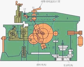
Figure 1 The main drive system of the B6065 head planer
1, 2 - sliding gear set 3, 4 - gear 5 - eccentric slider 6 - swing rod 7 - lower fulcrum 8 - ram
9—screw 10—screw nut 11—handle 12—shaft 13, 14—bevel gear
The transmission system of the B6065 planer is shown in Figure 1. The typical mechanism and its adjustment are summarized as follows.
(1) Shifting mechanism The shifting mechanism of Fig. 1 is composed of 1, 2 sets of sliding gears, and the shaft III has 3 × 2 = 6 kinds of rotating speeds to shift the ram.
(2) The gear 3 of the swing lever mechanism rotates the gear 4, and the slider 5 slides in the groove of the swing rod 6 and drives the swing rod 6 to rotate around the lower support point 7, thereby driving the ram 8 to reciprocate linear motion.
(3) The stroke position adjusting mechanism releases the handle 11, rotates the shaft 12, and rotates the screw 9 through the bevel gears 13, 14 . Since the screw nut 10 fixed on the swing rod 6 does not move, the screw 9 drives the ram 8 to change. starting point.
(4) ram stroke length adjustment mechanism ram stroke length adjustment mechanism is shown in Figure 2. During the adjustment, the shaft 1 is rotated, and the eccentric slider 7 is moved by the rotation of the small screw 2 through the bevel gears 5, 6. The crank pin 3 drives the eccentric slider 7 to change the eccentric position, thereby changing the stroke length of the ram.
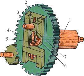
Figure 2 Adjustment of the stroke length of the ram
1—Axis (with square 榫) 2—Spindle 3—Crank pin 4—Crank gear 5,6—Bevel gear 7—Eccentric slider
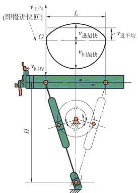
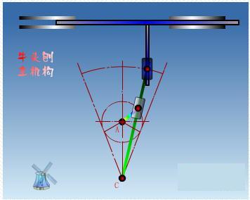
Figure 3 Variation of the reciprocating speed of the ram
(5) The change of the reciprocating linear motion speed of the ram The ram reciprocating speed is different at each point, as shown in Fig. 3. The working stroke angle is α, the idle stroke is β, α>β, so the return time is shorter than the working stroke, that is, slow forward and fast return.
(6) Adjusting the infeed mechanism and the feed amount The adjustment of the infeed mechanism and the feed amount is shown in Fig. 4. The gear 2 is integral with the gear 4 of Fig. 1. The gear 2 drives the gear 1 to rotate, the link 3 swings the pawl 4, and the ratchet 5 is turned to rotate the screw 6 by an angle to achieve lateral feed. In the reverse direction, since the pawl is inclined behind, the claw inner spring is compressed and the pawl slides over the top of the ratchet, so the horizontal automatic feed of the table is intermittent.
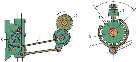
Figure 4 B6065 head planer movement and adjustment
1, 2 - gear 3 - connecting rod 4 - pawl 5 - ratchet 6 - screw rod 7 - ratchet cover
The amount of lateral feed of the table depends on the number of ratchet teeth that the pawl can move each time the ram is reciprocated. Therefore, the lateral feed amount is adjusted, and the position of the ratchet cover 7 is actually adjusted. The lateral feed amount can be adjusted from 0.33 mm to 3.3 mm.
Uv B Bulb,Uv Drying Lamp,Uv Lamp For Laboratory,Ultraviolet Light Lamp
Foshan Kingrate Optoelectronic Technology Co., Ltd. , https://www.kingrateuv.com