Eliminate compound tool rail technology (Figure)
Apply staggering technology and use a single tool rail in the right place to get the right tool rail application.
Moldmakers are always faced with the challenge of complex surface machining. The type of toolpath that is most suitable for vertical and near vertical surfaces is quite different from the toolpath that is preferred for horizontal and near horizontal surfaces. The decision about which toolpath to use and the exact application is made by the CNC programmer. These decisions are based on the experience and guesswork of how to obtain the optimum surface finish of a molded part.

Figure 1. The CAM system calculates whether a spiral tool rail is needed, how much and how many plunging angles are needed to achieve a constant roughness value for the entire part.
The mold manufacturer may choose any combination of these tool rails to machine the entire part. 
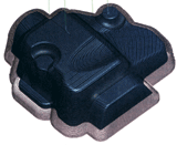
Figure 2. Contour processing.
Note: The light areas indicate the tool path jump and compound retraction motion when the tool is repositioned between the tool tracks. 
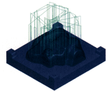
Figure 3. The staggered spiral path is based on contour cutting technology, which feeds the entire part in constant increments on the Z axis.
The combination of horizontal and vertical machining rails requires more tool retraction and more repetitive cutting. 
Figure 4. The staggered spiral path is more efficient, producing a more consistent surface roughness for the entire part and dramatically reducing the retraction motion.
The contour cutting path creates a tool path for the tool to feed in the Z axis at a constant increment.
Image Courtesy of Engineering Geometry Systems
Conventional approximation of surface machining For traditional CAM programming, the toolpath approaching from the side of the part (usually contour cutting) is common in vertical and near vertical surfaces; and the toolpath is approached from above the part (usually a projection milling technique) application Horizontal and close to horizontal surfaces. There are also toolpaths that travel along the exact ISO line of each surface. For composite surface parts, each surface has its own set of ISO lines—meaning that when machining between each surface, the tool has to retract and enter the new ISO line set. There will be many retreats.
The mold manufacturer may choose any combination of these tool rails to machine the entire part. Some of the problems with this approach are as follows:
- As the tool is frequently repositioned from one area to another, the composite toolpath requires a compound retraction motion of the tool. The more surfaces on a part, the more retraction motion the tool requires when changing from one type of tool path to another. Regardless of how precise the machine is, these movements must create seams due to tool wear, distortion, and the position of the front rail.
- Composite tool rails spend more time in designing, testing, and machining, and can cause inconsistencies in surface roughness for the entire part. Some of the toolpaths in a certain area obtain better surface roughness than the toolpaths in other areas, which requires the programmer to constantly adjust the machining parameters for each of the toolpaths.
- Depending on the tooling and CAM system specified processing standards, certain areas on the mold may require more processing time when the composite tool rails overlap. Moldmakers don't have time to process according to standards.
A better solution CAM system with intelligent processing capability solves these problems with a new type of tool path. This toolpath uses a single toolpath technology to intelligently apply an organic combination of contour lines and part-based projection machining paths.
The staggered spiral path is based on contour cutting technology, which feeds the entire part tool in constant increments on the Z axis. The CAM system first analyzes the slope and shape of the part's surface, and then uses the roughness value constraint to calculate whether a spiral path is needed between the contours. When the tool is still at the end of each contour cut, it moves to any light-colored area missed by the next contour cut and interleaved spiral cutters, removed before moving to the next contour cut material. Generates a continuous cutting path that matches the shape of the part with the least number of tool retractions (if there is a retraction).
The user simply specifies the maximum slope value at which the interlacing will occur and the maximum profile height at which the desired surface roughness is obtained. The CAM system calculates whether a spiral tool rail is needed, how much and how many plunging angles are needed to achieve a constant roughness value for the entire part (see Figure 1).
Interlaced spiral cutters produce:
- The most effective tool path based directly on the shape of the part
- Regardless of the slope of the surface, the entire part always achieves a consistent step and smooth surface
- Limited number of retracting movements
- Single rail shortens programming time
The technical comparison contour cutting path creates a tool path for the tool to enter the tool in constant increments on the Z axis. This is a quick way to generate a tool path, but for complex surfaces, the surface roughness on non-straight wall surfaces is unsatisfactory and the light areas are skipped completely unless the Z-direction increment is particularly small (see figure 2).
In order to efficiently machine horizontal or approximately horizontal areas, in addition to the contour guides, the CNC programmer must create additional projection rails. This is not just an additional step of processing, but rather an increase in the number of retracting movements and the generation of repeated machining trajectories in certain areas. This is a very inefficient part programming method (see Figure 3).
When the tool is machining the entire part, the staggered spiral guides first analyze the shape of the complex surface and then intelligently apply the most appropriate tool path (see Figure 4). Prospects The ability to accurately machine complex surfaces is critical to the success of moldmakers. By providing a processing strategy that not only produces excellent surface roughness but also saves mold maker time and money, CAM software developers who understand this need play an important role. The CAM system that implants smart products not only solves the problems faced by mold makers today, but also anticipates future needs.
The COVID-1 box of 9 common methods and rapid runny nose detection reagents are used for detection, the purpose is to determine the symptoms of SARS-CoV-2 infection simply and quickly, and it can sensitively determine the detection method of early infected people, which can be used for detection.
Virus-coronavirus twins such as SARS-CoV-2 need to be tested, and the test only takes 15-20 minutes.
The product is automatically produced and packaged in a 100,000-level purification workshop, and the shell is sterilized with 75% alcohol.

nasal swab test,nasal swab rapid test,nasal antigen test,nasal swabs for covid testing
Yong Yue Medical Technology(Kunshan) Co.,Ltd , https://www.yongyuemeds.com